Optical telemetry
Zedelef’s Optical Telemetry System allows you to harness all the benefits of an optical sensing network without replacing your conventional sensors. These include high bandwidth, intrinsic safety, electromagnetic interference immunity, long distance coverage and ability to multiplex
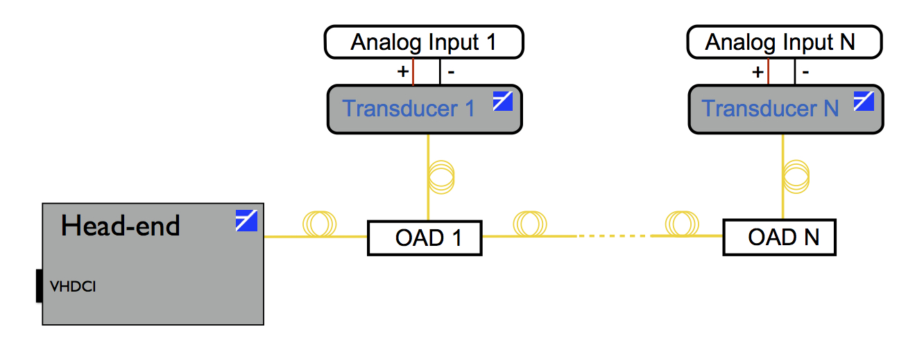
The system includes the Optical Transducers, converting an electrical signal into an optical one, the Interrogation Unit, that reads the optical signals and converts them back into electrical, and the optical network that connects multiple transducers with the Interrogation Unit.
The typical architecture is shown in the figure (click on it to enlarge). Each component is described in the sections below.
Key benefits
Irrespective of the specific field of application, Zedelef technology applies particularly in the following context:
- Distributed sensing: When monitoring must be done over large areas (over square kilometres) e.g. in the context of pipeline monitoring, electricity distributions, mining exploration, etc.
- Passive devices: In certain circumstances, our optical sensors are entirely passive, i.e. they do not require any power sources. For example, when used as voltage meter for high-power lines, the sensors – potentially distributed over many kilometres – require no power source and thus minimal maintenance (no battery replacement).
- Large sensor networks: Ocean surveillance, perimeter security, seismic surveying all require large number of sensors distributed over large areas. Our technology which relies on low-cost sensors and their ease to multiplex offers clear advantages over their electronics counterparts as the size of the network increases.
- Volatile atmosphere: In the presence of flammable or explosive atmospheres, it is generally not possible to use electronic monitoring. Our sensors can thus be used to monitor flow of natural gas and oil or for seismic monitoring in mines due to the presence of flammable methane gas or coal particulates.
- High data throughput: Distributed sensing can in a number of conditions be done wirelessly with a strong impact on throughput. Optical sensors, leveraging the capabilities of optical fibres can provided an almost unlimited bandwidth and therefore enable real-time monitoring at high sampling rates which is fundamental for certain application (e.g. distributed sonars, fault analysis in power distribution, etc.).
- Analogue transduction: In many sensing applications, analogue signals with the appropriate dynamic range are required.
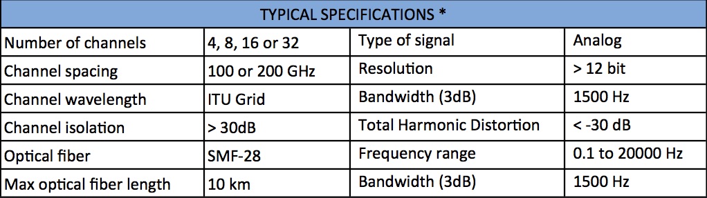
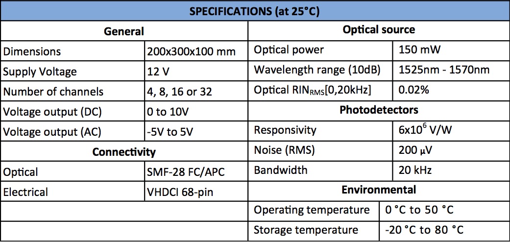
Typical Performance and Specifications of the Optical Telemetry System
- Combined with standard 200 GHz Add/Drop optical filters and Zedelef Optical Transducers, the Interrogation Unit can read up to 32 analog channels simultaneously and continuously with 12 bit resolution and channel isolation > 30dB.
- For the typical case of 4-20mA sensors we recommend to encode the output as a frequency with a voltage to frequency converter, which Zedelef can also supply on request. In this situation a resolution of 16 bit is typically achieved.
- Where a Fourier Transform analysis of the sensor’s signal is of interest, as in the case of hydrophones, our Telemetry System can detect signals with peak amplitudes as low as 10 μV.
Optical transducer
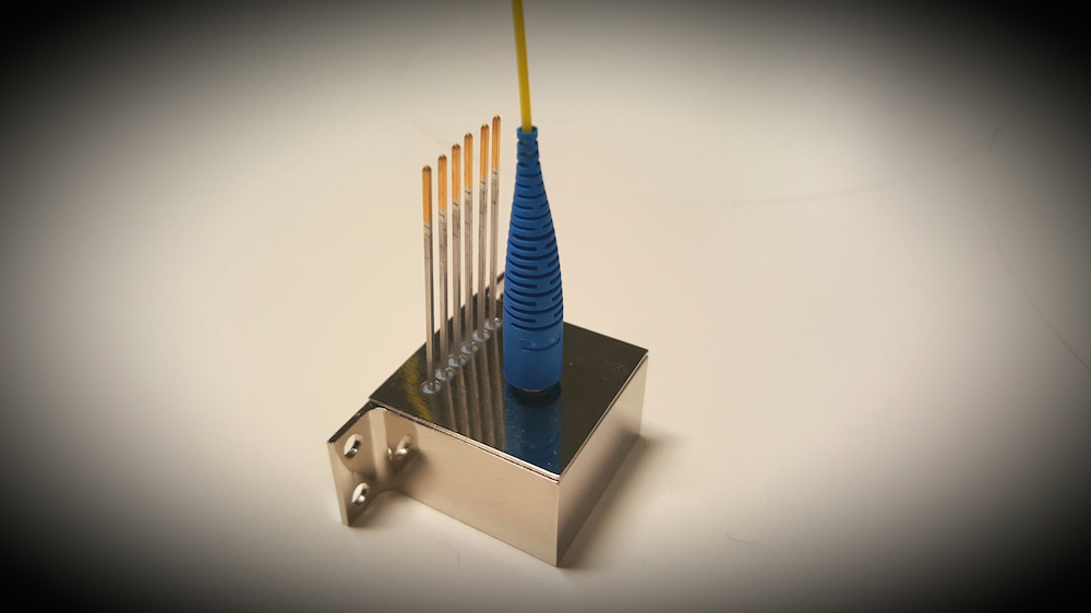
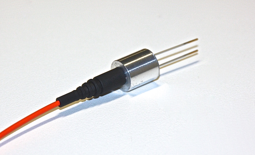
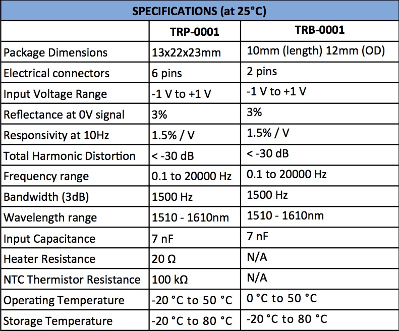
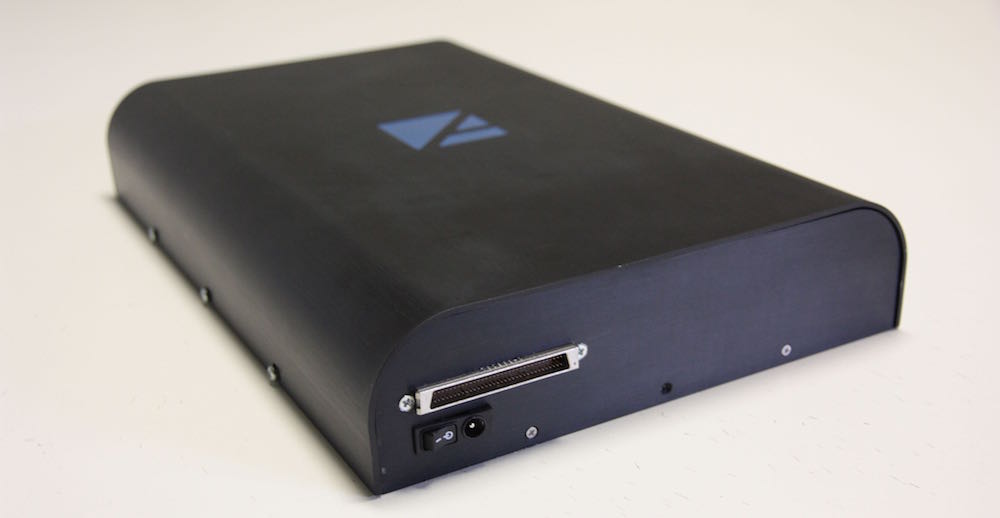
Our standard Optical Transducer (TRP-0001, top picture) comes in a small Kovar package (13x22x23mm) that can be mounted on a Printed Circuit Board. It features one optical fiber output (SMF-28) and 6 pins, 2 for an analog voltage input and 4 for the internal temperature sensor and heater. The transducer works from -10 to 50 degree Celsius, when using the internal heater, and from 0 to 50, without using it. Bandwidth is 2 kHz and the input voltage range is 0 to 2V, with a total harmonic distortion of less than -30dB. A compact version (TRB-0001, bottom picture) without the heater nor the sensor is also available. The principle of operation is described here.
Zedelef’s Optical Transducers can be connected to the electrical output of traditional sensors, e.g. piezoelectric, 4-20 mA loops or Variable Reluctance Sensors (VRS), to con- vert the sensor’s analog output into an optical signal. Up to 32 transducers can be interrogated continuously and simultaneously over a single optical fibre with Zedelef’s Interrogation Units. Our Optical Transducers can be connected directly to a piezoelectric sensor, e.g. a microphone, or a VRS. For 4-20mA sensors it is recommended to use a voltage to frequency converter (supplied on request) to convert the loop current into a periodic signal before connecting the Optical Transducer.
Interrogation Unit
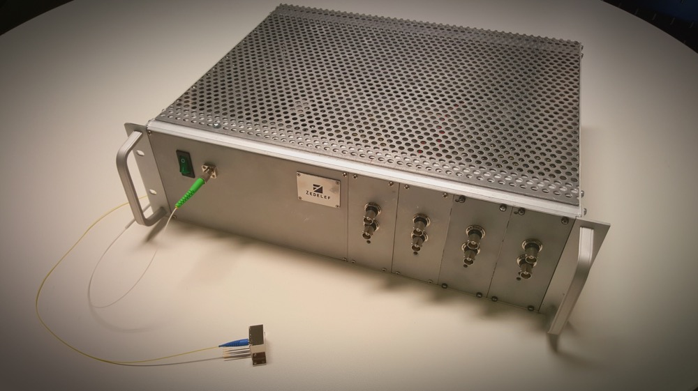
The Interrogation Unit has an optical fiber input (SMF-28) that collects the optical signals from the optical transducers and converts them into analog voltage outputs. It can read up to 32 analog channels and it features a VHDCI connector for easy interfacing with most industrial data acquisition softwares (top picture). For small channel counts it can have BNC connectors (as in the bottom picture). Inside, the Interrogation Unit hosts a light source, various optical components and photodetectors to accurately measure the reflectance of each transducer and convert it into a voltage reading.
Optical network
The optical network consists of a single mode fiber SMF-28 that connects multiple transducers in a daisy chain. We use a Dense Wavelength Division Multiplexing scheme, where a specific wavelengths are assigned to each transducer. In order to do so, the network makes use of Optical Add/Drop filters (OAD). Such an architecture is derived from telecommunications and can accommodate up to 72 channels on the standard ITU grid. All the optical components used in the network are standard and routinely used in telecommunications.